Service Downloads Remote support +49 5622 930807-0 DEEN
Describe your taskEnquiry

Custom machines · xMS

Your measurement task. Our machine.

When standard devices fail on your part, we build the measuring system for it. We develop mechanics, electrics and software ourselves. That is why everything fits together in the end, from handling to the connection to your PLC.

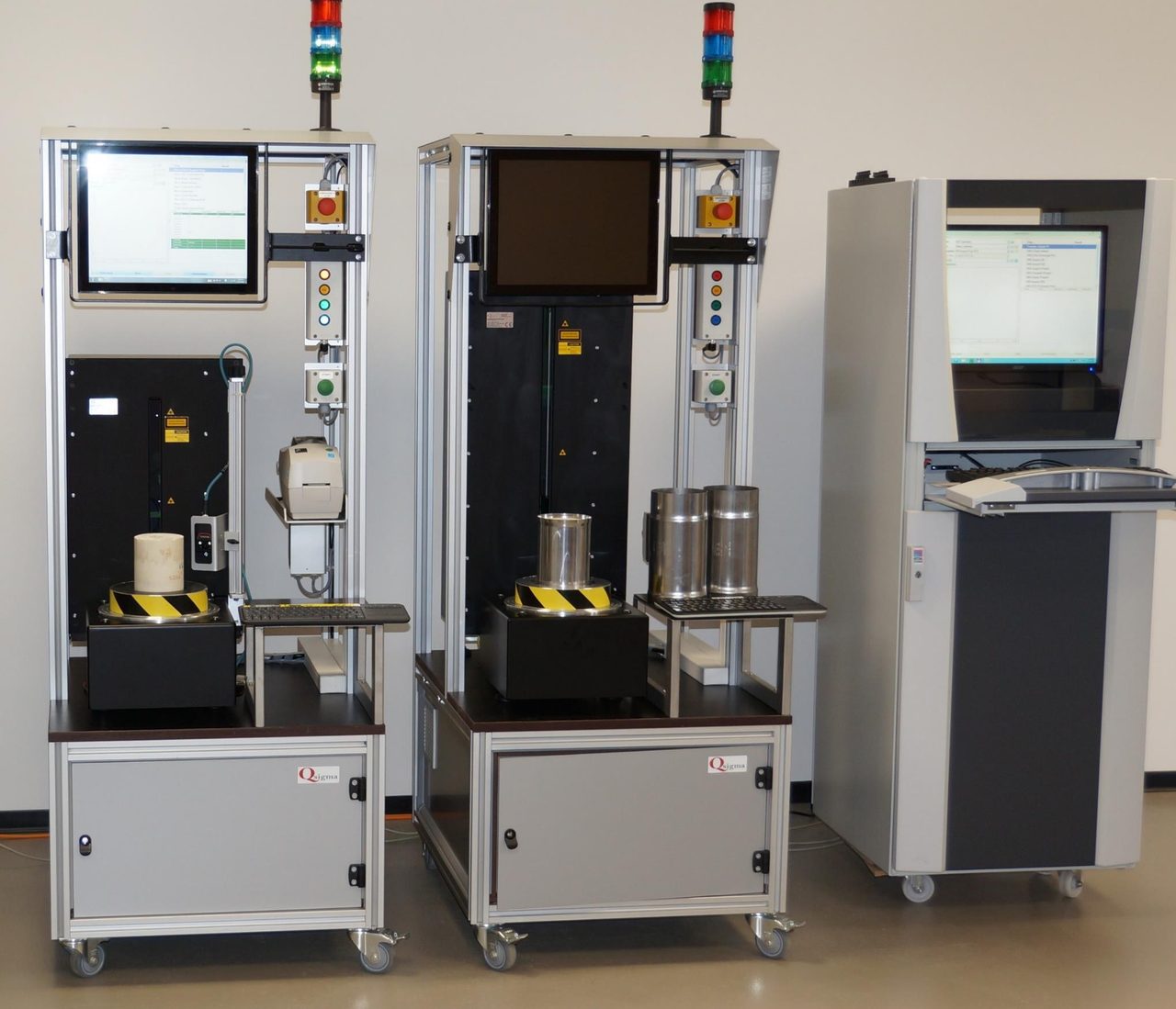
Three Qsigma measuring systems side by side in the hall, with screens and signal lights
Qsigma measuring systems · designed and made in Germany

What we adapt

The system follows your part.

Mechanics, sensors and software are adapted to the measurement task, not the other way round. Because everything comes from our own development, the parts work together.

  • Mechanics

    Fixture, frame and axes for your part.

    From a small test part to a large roll. Our systems measure springs up to 650 mm high and rolls up to Ø 520 mm.

  • Handling

    Manual, on a turntable or in the line.

    Handling depends on cycle time, quantity and part. Positioning should not require special knowledge.

  • Sensors

    Laser and camera, freely combined.

    Laser point and line triangulation, red and blue laser line, cameras for profile projection. Several sensors can be arranged freely.

  • Evaluation

    Evaluated to your specifications.

    Contour, roundness, diameter, nominal/actual comparison with CAD, to DIN EN ISO, ASME or OEM specifications. With InnoMeas, our own software.

  • Integration

    Integrated into your line and your data.

    PLC via PROFINET, EtherCAT, S7, MELSEC, Modbus/TCP or TwinCAT. Results to qs-STAT, to databases or in your format.

  • Long term

    One team for hardware and software.

    The rights to software and design remain with Qsigma. Adaptations and service therefore come from a single source, even years after commissioning.

Measuring principles

Four methods that we combine.

Which method fits depends on the part, the surface and the cycle time. We often combine several in one system.

  • Diagram of laser point triangulation: a laser point hits the part, the receiver sees it at an angle. Sensor Distance LaserReceiver

    Laser point triangulation

    A laser point hits the part. From the angle at which the receiver sees it, the sensor calculates the distance. Very finely resolved, 1.5 to 3 µm in the CMS.

  • Diagram of laser line triangulation: a laser line captures the entire surface profile at once. Sensor Profile

    Laser line triangulation

    A laser line captures an entire profile at once, up to 10,000 profiles per second depending on the sensor. With a blue laser, also on semi-transparent plastics.

  • Diagram of profile projection: the part stands in backlight, the camera captures its contour as a silhouette. BacklightCamera

    Profile projection with a camera

    The part stands in backlight, and the camera captures its contour as a silhouette. Fast for outlines, dimensions and codes.

  • Diagram of grid scanning versus path tracking: on the left a fixed grid scans the surface, on the right the sensor follows the contour. GridPath tracking

    Path tracking instead of a grid

    Instead of scanning the surface in a fixed grid, the sensor follows the contour and adjusts its position. This keeps it within the measuring range even on unknown shapes.

Feasibility

First find out whether it works. Then build.

Before you invest, we check whether and how your task can be measured. You talk directly to the developers, not to a ticket system.

Request a feasibility check

What helps us

  • drawing or CAD model of the part
  • photos, also of the part in production
  • material and surface
  • features and tolerances
  • cycle time and quantity
  • sample parts, if possible

What you find out

  • which measuring principle fits
  • which accuracy and cycle time are realistic
  • what handling and integration can look like
  • the next steps: concept and quotation

Process

Five steps to your measuring system.

From the first conversation to service, you have one contact for hardware and software.

  1. 01

    Enquiry

    You describe the part, features, accuracy and cycle time. Drawings and photos help with the first assessment.

  2. 02

    Feasibility study

    You find out which measuring principle fits and which accuracy and cycle time are realistic.

  3. 03

    Concept and quotation

    You receive a system concept covering mechanics, sensors, software and integration, together with the quotation.

  4. 04

    Development and build

    We design, build and program the system ourselves. You talk directly to the engineers throughout.

  5. 05

    Commissioning and service

    We commission the system at your site and stay available, remotely and on site.

Examples

Built for one task.

Systems and evaluations from our custom machine building. Each of them started with a measurement task for which there was no suitable solution.

TMS measuring system with signal light and screen
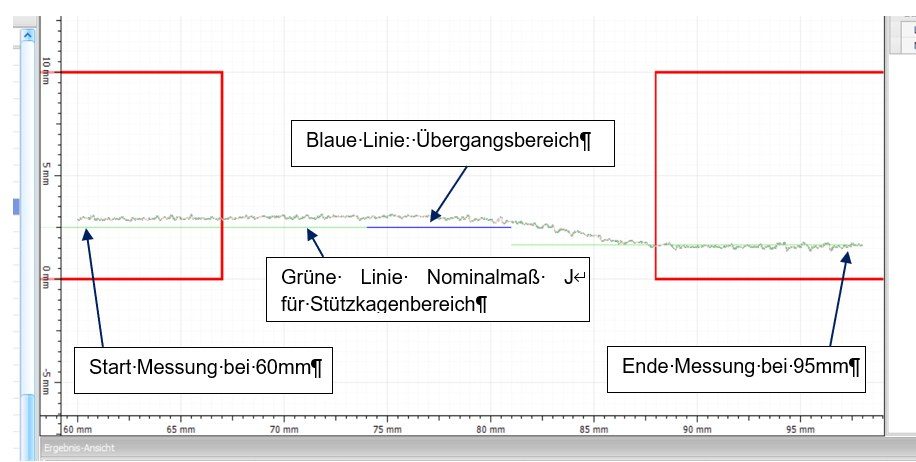
Evaluation of the thickness measurement with measuring ranges and transition zone

TMS · Thickness measurement

Thickness of flexible structural parts, repeatable to 5 µm.

Two sensors in a twin sensor design measure the thickness of the part. The system captures four vertical sections of 150 mm each in 12 seconds.

Repeatability
5 µm
Measurement
4 sections of 150 mm
Measuring time
12 s
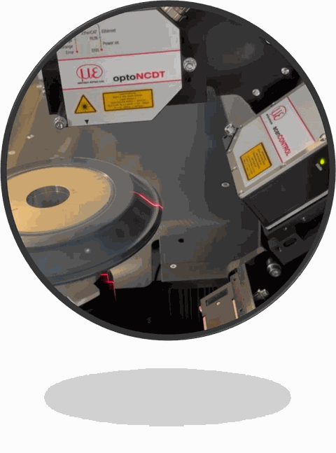
Inside the BMS: two Micro-Epsilon laser sensors above a part on the turntable

BMS · Hydrogen

Boss parts for hydrogen pressure tanks.

Several line sensors are arranged at free angles; a 90-degree grid is not required. Sensor types can be combined: red and blue laser line, different line lengths.

Sensors
several line sensors
Arrangement
free angles
Laser
red and blue
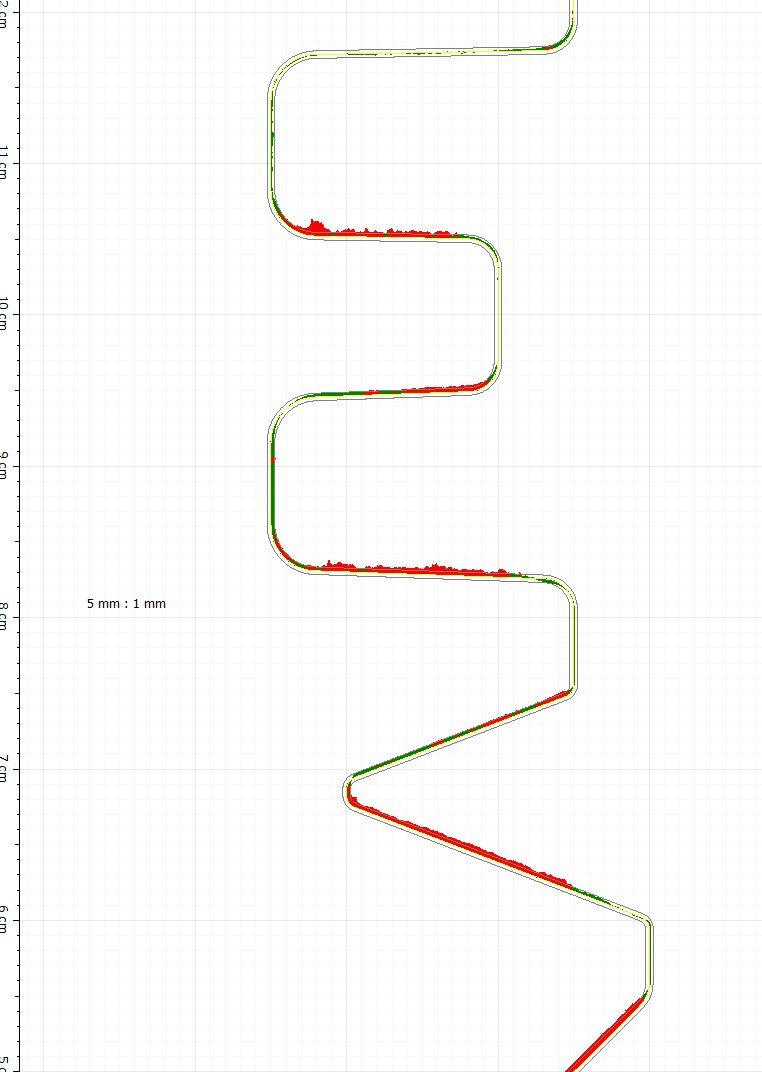
Contour evaluation of an open profile, deviations marked in colour
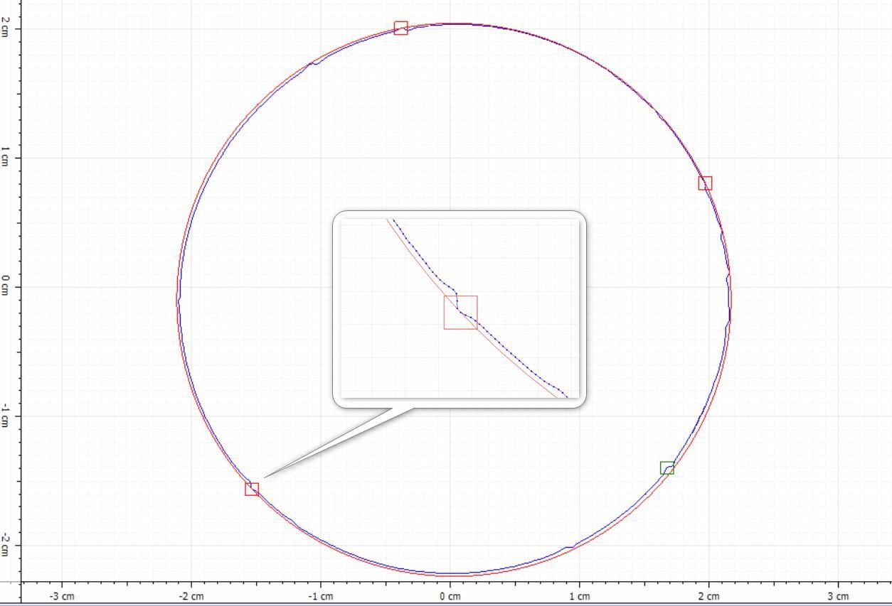
Roundness evaluation using the minimum circumscribed circle method with an enlarged detail

xMS · Evaluation

Evaluations that fit the task.

For custom systems, we develop the evaluation in InnoMeas to suit the task: contour comparison of open profiles with deviations marked in colour, roundness using the minimum circumscribed circle method and other reference methods.

More about InnoMeas

From automotive to your industry

Automotive know-how for your production.

In the automotive industry, our systems measure suspension springs and exhaust aftertreatment components to the standards and specifications of Volkswagen, Mercedes and GM. We bring this experience with tight tolerances, inline inspection and PLC integration to every industry that manufactures goods and where accurate measurement pays off.

Your industry is not listed? Tell us about your measurement task.

Describe your measurement task

Do you know someone with a similar measurement task?

Contact

Tell us about your measurement task.

You talk directly to the engineers who build your system. Drawings and photos help us with the first assessment.

Phone
+49 5622 930807-0
Email
info@qsigma.de
Address
Qsigma GmbH, Brautäcker 4
34560 Fritzlar, Germany
Service
remote and on site · Service and support